Wednesday, January 29, 2014

OT Install Finished

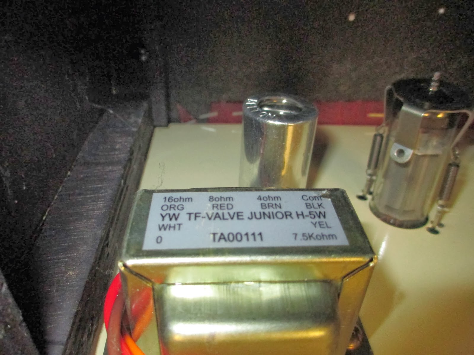
I drilled a hole for the larger Hammond OT using a 11/64" drill bit on a high torque setting, since I was drilling through a metal casing. I then fed the brown and blue wires through the wire hole, since they have the connectors on them and need more room. After that, I fed the rest of the wires in and secured the OT down with the screws and bolts. I connected the brown wire to T4 and the blue wire to T3 using the quick connectors. Then, I soldered the yellow wire to the 16 ohm output, the green wire to the 8 ohm output, the orange wire to the 4 ohm output, and the black wire to ground. The white wire would be for a 32 ohm output, but since I am not installing one, wrap this one up with electrical tape.

The soldering was very easy: just heat up the already existed solder that was left from the old OT, and push the wire through the hole. I added a little bit extra solder just in case. Finally, I wrapped up all the wires with electrical tape to get them out of the way. I also found this spring reverb unit by Accutronics today, so I'm going to learn about how it works. I want to test the amp today, but I can't bring it home because of the great Snowpacalypse of Auburn 2014.

Feed the brown and blue wire first.

The new hole for the OT drilled on the far right.


All wires pulled through.


Brown wire to T4.

Blue wire to T3.


Solder these in as shown.

Cut the excess wire.

Sweet, a reverb unit.


Springy.

Wednesday, January 22, 2014

Speaker Install, OT Removal

My speaker came in, so I installed that into the cabinet. That was the easiest mod ever.


New 12' speaker


8 ohm.

Made on 1.34.2005?

Screwed into the grill.


I also took out the original OT, which was a pain. You have to hold a bolt on the bottom of the chassis with a wrench, and then turn the screw on the top. These were torqued super tight. 

You have to hold this to unscrew the OT.

Screws out of the OT.

Place a cable from ground (amp casing) to all components
to ground them before you touch the board.

Cut these to remove the OT wires. 

4, 8, and 16 ohm outputs.

New OT (top) vs old OT (bottom).

The Hammond 125-ESE is a 15-watt peak, vs the stock 5-watt peak.
I also wrote up a wiring diagram for installing the Hammond 125-ESE, since the wire colors are different on the original OT and the Hammond OT.

Output Transformer schematic, new on left, old on right.
There is no 32 ohm output on the amp, so I will not be using
the white wire.

Labels of where the new wires go.
I also crimped on some connectors to the blue and brown wires of the Hammond OT, which clip on to the amp's main circuit board. I used the same connectors from the stock OT since I could not find any more connectors that were the right size in the SPaRC Lab. I then soldered these connectors, but I made sure to put the connector cover on first! I didn't do that originally, then realized that the connector cover would not fit with the connector already attached to the wire.

I soldered these old connectors onto the wires going to the main board.

Don't forget to put the connector covers on before soldering!


Tuesday, January 21, 2014

Amp Teardown

I finally got my amp and cabinet to the SPaRC (Student Projects and Research Committee) Lab in Broun Hall. I first had to take off the back of the amp head, which was just a few screws and it popped right off. I then took out four screws on the top of the head and then pushed the screwdrivers through each of those holes to push the actual amp up. Then the amp slid very easily out of the housing. I forgot to bring the output transformer, but that will be installed soon.

Transformers.

Robots in disguise. 

Out of the casing!

The main board. 

Speaker outputs.

Power switch.

These four screws are the ones to remove.

Monday, January 20, 2014

Updated Cabinet, Transformer has Arrived


My transformer, a Hammond 125-ESE (15-watts) arrived this week, and I also painted the speaker cover grill thing on the cabinet. It is now blue, an upgrade from faded black, and I think it looks great. All that from a $2 bottle of spray paint. Pictures of the output transformer and updated color follow. 


Wiring diagram.


Faded black to start.

Taped up the edges.

Coat one. 


This is the spray paint I used. 

Round two. 

Installed. No speaker yet. 

America.